CSC 103: How Computers Work
Lab 1: Logic Gates
Due: to be turned in as part of the first homework
Summary:
You will experiment with a free logic simulator during class.Preparation
Logisim is a free graphical tool for designing and simulating logic diagrams. If you are working on your own machine, make sure you have Logisim downloaded.If you are working on one of the lab machines, first make sure to log in under the Mac option (this is because Windows has some issues and it takes about 10 minutes for it to start up). Then download the Logisim jar file from here:
Save it to the Desktop. Then open the Terminal (Applications -> Utilities -> Terminal). Then type in the following line, replacing "ssheehan" with your account name:
java -jar ~ssheehan/Desktop/logisim-generic-2.7.1.jarOr if it automatically went to the Downloads folder, replace "Desktop" with "Downloads". Either way, you should eventually see a picture that looks something like this:
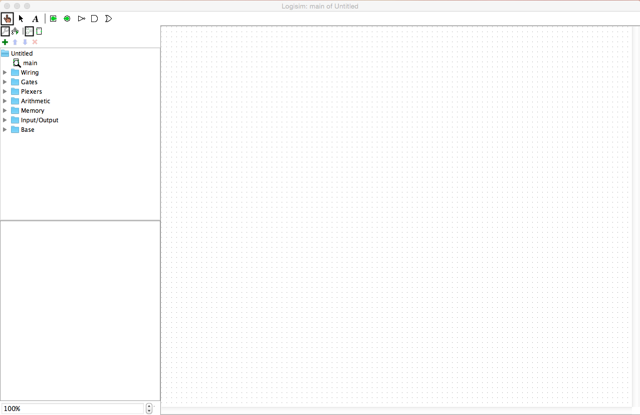
Part 1: NOT, AND, and OR
In this part we will create the three main logic gates one at a time, in the same project. First, familiarize yourself with the Toolbar at the top:
From left to right, these tools are:
- The "poke" too, which will toggle inputs between 0 and 1.
- The "wire" or select tool, which you can use to draw wires
between inputs, gates, and outputs.
- The "text" tool, which will allow you to label features of your
circuit.
- The "input" tool, for creating new inputs.
- The "output" tool, for creating new outputs.
- The "not" gate.
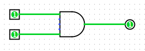
- The "and" gate.
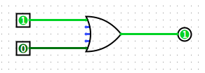
- The "or" gate.
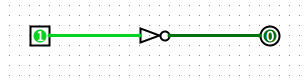
We will build each circuit in turn, starting with the NOT gate, as shown below. Build this circuit, then use the "poke" tool to make sure it corresponds with the truth table for NOT:
Part 2: XOR
Now we're going to create the XOR (exclusive OR) circuit shown in class. This circuit represents "one or the other but not both". Refer to your notes, or use the truth table to build up the circuit. You can save the first part, or overwrite it. Make sure to test each of the 4 combinations of inputs.
Part 3: Half-Adder
Consider the problem of adding two bits x1 and x2. Here s represents the "sum" or the rightmost bit, while co represents the carry (carry out).- Complete the truth table for this problem, which is called a
"half-adder."
x1 x2 co s 0 0 0 1 1 0 1 1 - Building upon your XOR gate from the previous part, create a circuit for the half-adder. Use only NOT, AND, and OR gates.
- Label your input and output pins with the text tool (and also create a text box at the top of the circuit to say what it is).
- Test your circuit. It should display the sum of the two input bits, which will always be 0, 1, or 2 (displayed in binary).
To finish up
After you're done, show your project to me. Save your project (you'll turn in the half-adder part with Homework 1). If you have more time, you can try creating an adder for 3 inputs, or you can begin on the homework.
Credit: based on labs by Jerod Weinman and Dominique Thiebaut